Friday 30 December 2011

The Plan!

Have pretty much settled on the modules and designs for 6 panels. Nearly all the PCBs are here, panel designs are not all finalised, so there may be some changes. Feel free to send me suggestions. I have a few proto-type modules in mind that may get into Panel 5 if they work out.
So
Panel 1 - bindubba 1 & 3 sequencers, multiples (banana to minijack connectors)

Panel 2 - PMS VCO, PMS VCO, dual DC mixers, LDR VCA/mixer, dual LFO, utility EG

Panel 3 - 5 stage Resonator, dual triple channel VCAs, double Jerkoff Chaos, EoE VCF (transistor ladder),  ARP/Electronotes style 2 pole VCF, Divine CMOS (sub-oscillator, harmonic divider, harmonic ring-modulator, pattern generator, all kinds of tricks!)


Panel 4 - CMOSC (6 simple CMOS drone oscillators with gate selectable frequency control and sync function), 4 stage Thru & Hold, 4 stage Sample & Hold (these each have CV inputs and 4 individual gate controlled outputs), Four Squared Logic, The Great Divide, 8-bit Cipher, dual bi-directional switches.


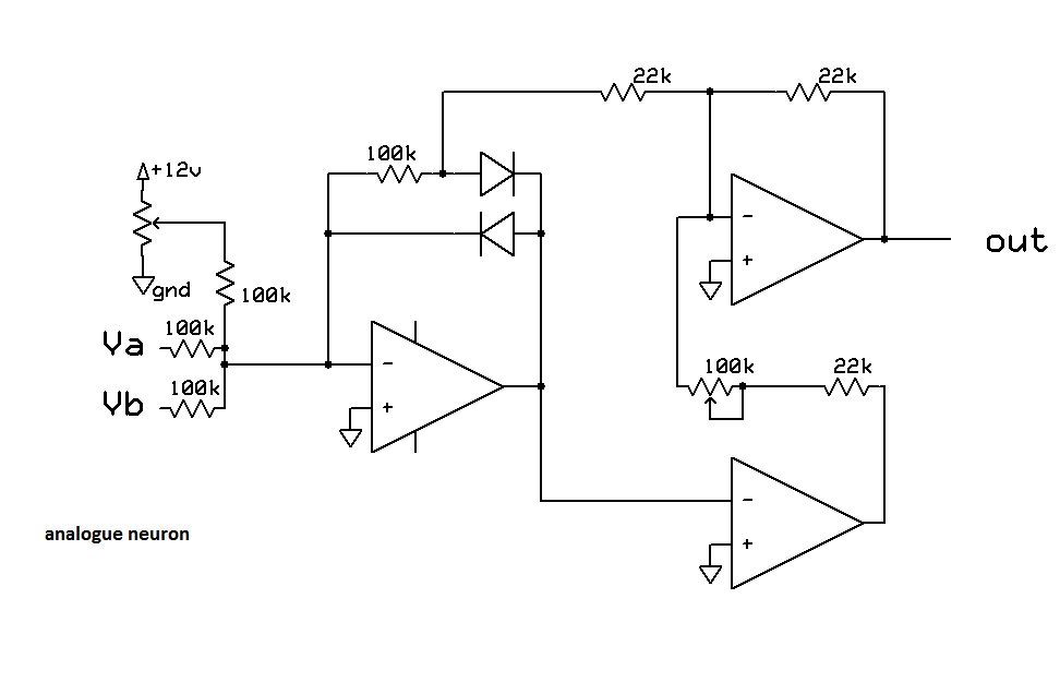
Panel 5 - two Envelope Generators (based on Korg 3100 designs but modded for CV control of Attack/Decay, extra outputs and retriggerable), dual DC mixers, four Utility VCOs (these are 1V/oct and range from approx 0.1Hz to 8kHz so can be used as LFOs too), twin-T VCF with voltage controlled resonance, VC Wave Clipper, dual analogue Neuron.

Panel 6 - PT2399 based delay, Ramp generator, dual Utility VCOs, Veena (drone module based on Indian musical instruments), Six channel Mixer/Panner with headphone amp and multiple outputs (banana and 1/4 inch), Six Random Noise sources (pink, white, slow random, etc), Six Passive filters (Vibes, Vox, Brass, Funk, Harp, Gurgle - to use with extra outputs from Veena), The Bigot (CV controlled signal splitter), analogue And, Analogue Or, Controller (module for adding proximity or ribbon controller)

Thursday 22 December 2011

8-bit cipher / Great Divide / 4 squared Logic

this is a quick 'behind the scenes' vid of the above named modules. Probably best to read about them from the build files found on my DIY/data page.
I sold a few boards of these designs for DIYers, but they will also be included on the CMOS panel (panel #4)

and just to offer best wishes to everybody for New Year and Xmess, here's some pics from the Sub Ordnance xmas show (I'm the ass hat elf playing the Library Serge)

nonlinearcircuits vids not by nonlinearcircuits

These panels now reside on the other side of the country........

also this one
and


VCO User guide

Just a basic description of the ins/outs and controls to get you started (300kb)
VCO User guide
btw - email gets to me at:

Friday 9 December 2011

Sequencer panel quickstart guide vers.1

feeling all corporate
A few basic patches and an attempt at a functional description.
I will refine this in time, so consider this a first draft.
SEQUENCER PANEL USERS MANUAL (draft)

Sunday 4 December 2011

PCBs and Build Manuals

If you have bought a PCB from me and want to find out what all the unmarked resistors are and other pertinent information. Most likely you will find it HERE

Saturday 26 November 2011

VCO panel

been playing with the sequencer panel and VCO panel together.  kinda pleased; the phase modulated sync, CV pan pulse and CV processed saw functions on the VCOs make for some pretty interesting sounds.

Friday 4 November 2011

analogue neurons

this circuit was in a paper I had to read, it looked interesting so i built it with a few mods to suit synths. It can do a few different tasks, fed an audio signal and an envelope it can be a resonator/wave multiplier/gate. Fed two CV signals it turns them into something else. in the vid it is getting two LFO signals, as you can see, the output is all over the place.
Its a fun, unpredictable & simple circuit, so designed a dual version PCB for it, guess that will be on panel #4 or 5....


Friday 14 October 2011

VCO panels arrived

got these today
stuffed in the bananas and sat knobs on top just to get an idea of how they will look. All the PCBs have been tested. Two VCOs with pan-pulse and sawtooth processor wave-shapers, two mixers, two LFOs, 1 VCA (with 3 input mixer) and an Envelope Generator


Friday 23 September 2011

5 stage 555 resonator

demo of this module

4009 bleeding VCA

This is a layout for a dual VCA module. Each VCA has 6 separate inputs and outputs. All 6 are controlled by the same CV/gain pot settings. The VCAs are built around cmos 4009 inverters. The PCB is rather compact, 26 electros, 4 ICs, 6 pots and well over 100 SMD resistors in 1.3x5.5 inches. Resistors are mounted on the top and bottom of the PCB.
'Bleeding VCA' is a hint as to the ...erm... feature of this module. The overworked 4009 chips is going to suffer. Anyway it is a unique VCA, the panel will have 4 attenuable CV inputs, 2 initial gain pots, 12 AC signal inputs and 12 outputs.

trying out some filters and a chaos module

Monday 5 September 2011

Full metal yodel at the Artifactory

Wednesday 31 August 2011

SEQUENCER PANEL

finally stopped testing new designs and actually started 'production'
The 1st panel is completed and worked straight away = nice!

A user manual for the Sequencer panel can be found HERE


The 2nd vid is by Jono

Friday 26 August 2011

5 more

tested and working
1. Tb303 filter clone with CV inputs for Cutoff, Mod and Decay.
2. Filter based on the Arp4023 with added gain bandpass output and modded for LM13700 OTA, this also serves as a pretty decent VCO when the Q pot is set accordingly.
3. LDR based VCA, based on the one found in the Korg PS3200 and a schematic from an old Japanese diy magazine.
4. dual LFO, standard op amp based LFOs, with pots to change waveshapes
5. 5 stage resonator; an extended version of the 3 stage 555 generalised resonator found in Electronotes. It certainly works and is interesting but not entirely sure I like it yet, will probably seek a 2nd opinion

As usual, minimal wiring required


Friday 19 August 2011

new modules tested

got a bunch of boards in this week, which distracted me from building sequencers. Just had to see if they worked.
So there is a basic envelope generator, all trannie core circuitry, just an op amp on the output to get 0-6V levels.
The crossbreed waveshaper/sequencer thing...not really sure what to call it. Feed it two VCO signals and it will divide them down by /2, /4, /8 and /16, plus AND gate various divisions from each input signal, then all of these 12 signals and the original inputs can be nulled or mixed to deliver a rather chunky output. If you feed it two slow clock signals you get a sequencer...of sorts, nothing like any other sequencer out there.
The dual mixer is simply two three input, single output DC mixers, nothing special but essential.
The VCO is as described below, haven't fully set it up yet but have had it running and it seems to work beautifully. As for wiring, not counting power lines, the Crossbreeder needs 3, EG needs 2, Dual mixer needs 8 (bugger!) and the VCO needs 0 (perfect)
So far all boards have worked fine, with no trouble-shooting or kludges at all. I had a Coopers Pale tonight!

 Crossbreeder & EG
 Crossbreeder & EG
 Dual Mixer
 VCO
 VCO

Tuesday 2 August 2011

panels

I got panels
These are raw aluminium 2.5mm, CNC'd panels, with the labels screenprinted/baked on and look great.
I like raw metal but will test one to see how it goes with a clear sealant, mainly to protect against Twistie fingers.

Thanks to PNEgraphics for doing a great job.


Wednesday 27 July 2011

zip file for sequencer panel layout

can be found here
always good to check the bindubba PCBs thread at muffwiggler for updates, questions from other builders and probably some answers

Wednesday 6 July 2011

new modules and progress

Sent off an order for a bunch of pcbs today. Heres the screenshot:

More bindubba1 & bindubba3 sequencer boards, a basic dual mixer, a 'crossbreed sequencer/waveshaper', two VCOs and jack/led/power breakout boards.

The Crossbreed started out life as a cross product generator from Electronotes using TTL chips, this version uses CMOS, which means less chips and less current draw. Anyway it can be fed two signals from VCOs, usually best if they are almost the same frequency, but not quite the same. The divisions and harmonics from these signals are then combined adjusted to obtain thicker (literally) waveshapes or carefully set up to create your own original animated waveforms. Animated because you can of course modulate the VCOs and obtain continuously changing waveshapes. Guess I should record some demos and post some oscilloscope shots for this to make sense......okay soon.

The name "Crossbreed" has two implications, one is the output is an audio waveform obtained from divisions and combinations of the input audio rate signals. The other is that this module can also function as a sequencer providing extremely complex and interesting patterns as a result of being fed two different clock signals.

The VCOs are functionally based on the Aries AR-338 PMS VCOs. The AR-338 was built around the SSM2030 VCO IC, which is now very rare. So I used the well-known Mikulic sawtooth core from Electronotes (used in many VCOs - CGS, MFOS, ASM) and dressed it up a bit to get the AR-338 functions.
So what does it do? It emits sawtooth, triangle, pulse, processed saw and pan-pulse outputs. The pan-pulse is cross of the pulse and triangle waves which can be modulated by CV, it actually looks like the signal from Ian Fritz's double pulse waveshaper, although the circuits are completely different.
The processed sawtooth can be adjusted to obtain a variety of waveshapes or CV can be used to morph it between different shapes.
Now the PMS bit, which means (in this case) "phase modulated sync". Usually VCOs can be sync'd together in different ways, soft sync and hard sync (google it). The PMS function allows the sync to be shifted to different parts of the syncing signal; the rising edge, falling edge or anywhere in between. Of course it can be CV'd to give... (well fk me@!) phase modulated sync!
Guess I will get some mp3s and 'scope shots up soon to make this clearer.

Panels for the sequencer boards are being manufactured this week and should be ready soon. They look much the same as the paper-faced proto-type a few posts down but are bare aluminium with baked on black labelling. The company manufacturing them also do panels that are used in many radio & TV studios around Australia, so I am expecting them to be excellent and durable.
Have also ordered 2000 knobs, Davies 1900H clones in yellow and purple

Saturday 25 June 2011


This soundtrack was made with the bindubba1 sequencer controlling 4 VCOs. The VCOs were connected to VCFs and wave multipliers, all CV'd by the bindubba1 as well. During record I just changed the song sequencing switches and the levels on the mixer.

Friday 24 June 2011

PCBs for sale

 These are protoype PCBs, 9 are available ( now 7?). The one above is a bindubba1 shift sequencer. One set of boards is $25 plus shipping. One breakout board is for LEDs and binary count gate outputs, the 2nd is for the 16 control voltage outputs.
It is a wonderfully easy sequencer to use, one clock input gives 16 different but related control voltage outputs which can be used for brain-twisting convoluted melodies, the switches can be used for 'song sequencing', plus it gives 8 gate signals which are divisions of the input clock (perfect for driving the bindubba3 - below).

The boards are connected by 40 pin IDC cable (same inside your PC = cheap), so wiring is very easy. Building the PCB itself is not so easy, the components are VERY densely packed. Good soldering skills and a fine tipped iron are essential. The boards need one mod: cut a trace and add a resistor. It was a problem that didn't show up on the vero-board version.

More info on the design and some demos can be found HERE. Pots and switches can be mounted on the PCB. The breakout boards are connected to LEDs and jacks by wire clippings. I used clippings from LEDs which are quite stiff and the boards are held on very well with no need for extra mounting. Pictures of the mounted boards at the bottom.


The pictures below show the bindubba3 polydirectional sequencer. These are protoype PCBs, 9 are available (7?). One set of bindubba3 boards is $35 plus shipping. Again pots and switches are mounted on the PCB and some sections are very densely populated, so good soldering skills are essential.
This sequencer is really quite fun to use and can be patch-programmed to operate in a variety of different patterns. You can do the old school count up from 1 to 16 if you wish but it can do so much more. More info here The schematic in the link is an early version and will be updated soon.

Watch the vid to see the bindubba3 in action, various patterns from different reset programming patches can be seen.

Now the bad news, this board requires a number of mods to get it to work. A minimum, to get it working, is cut one trace, add two jump-wires and 8 resistors...not too difficult. To get full patch-programming functionality it needs another 7 traces cut and about 7 jump-wires added.

I go by andrewF on muffwiggler and electro-music and can easily be found on either forum. Discussion of these designs can be found on the muffwiggler DIY forum. Build info will be provided for those that buy the PCBs.


Monday 6 June 2011

coming soon

bindubba sequencer panel
vco panel
relay panel
cmos panel
meat & 2 veg panel
http://www.sdiy.org/pinky/