Monday 31 December 2018

Signum Hyperchaos

This is an expansion of Primal Hyperchaos, based on the description in a paper by C Li, et al. The internal signum switch has been brought out to the panel. It can be used as a stand-alone switch (don’t expect it to be clean and nice) or it can be used to inject signals into the hyperchaos circuit or control the switching of the hyperchaos. Some actions will make the oscillations stop; others will make them go nuts; experiment! 

It can be built to run at different speeds simply by installing different capacitors. Very easy build, no special components needed.
There are 5 different CV outputs and 1 gate output. The CV IN is associated with the CLIMAX pot which determines how high the peaks go. The module can be greatly influenced by the CV in signal and can exhibit some fairly nutty responses at times. 

IN1 and IN2 are the inputs for the Signum switch, they are also connected via their switching pins to the internal workings of the hyperchaos circuit. SW2 is also the internal switch for the hyperchaos circuit so if you use this input you will find that switching only occurs with an external signal. Use SW1 if you want to control the switching of the hyperchaos with an external signal.

As ‘signum’ implies, the switching signal is +1 or -1. This means you need a signal crossing 0 to make switching occur. A regular gate may or may not work, depending whatever else is going on at the time. The signum output is also the W output, as indicated on the panel. 

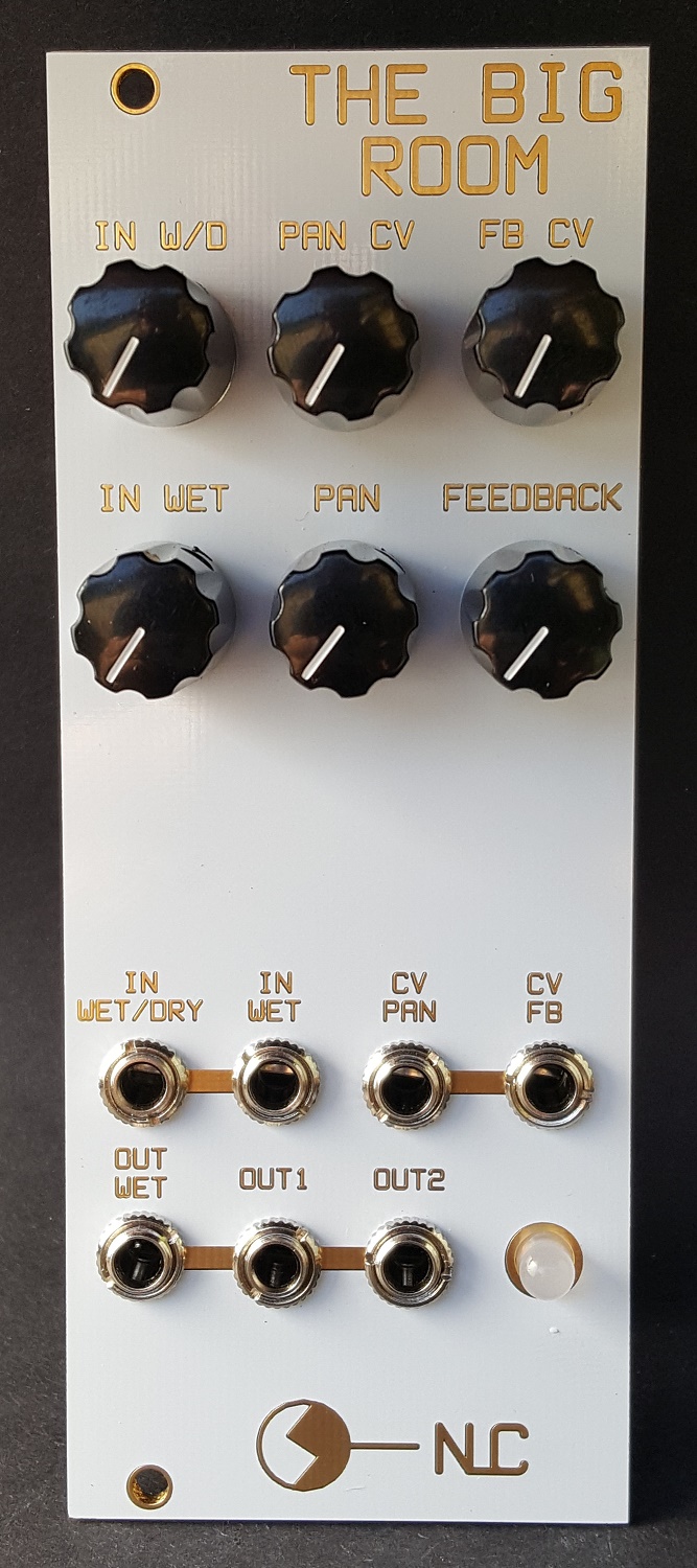
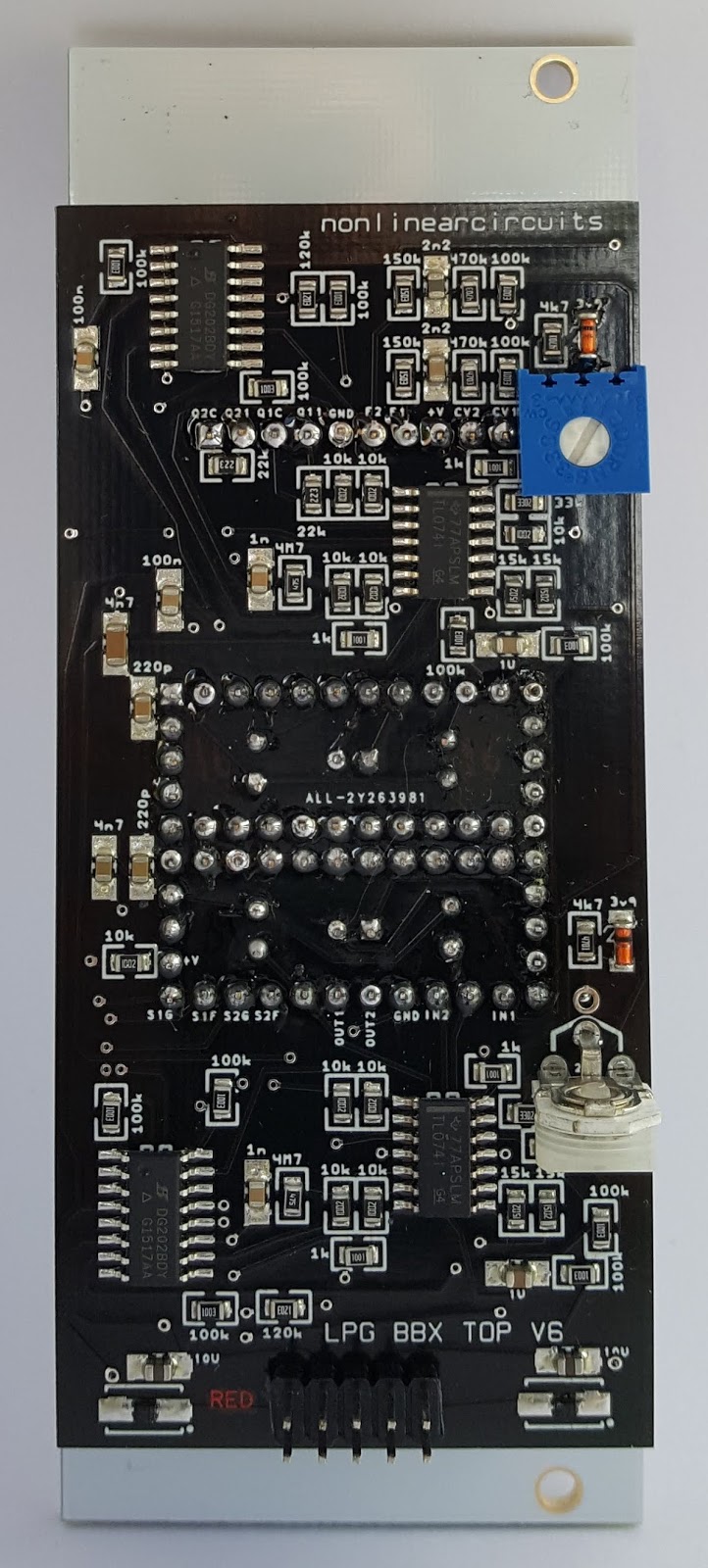
Build guide & panel template


GENiE - GEneralized Nonlinear Extrapolator

GEneralized Nonlinear Extrapolator 

This module is made of 3 neuron circuits and a difference rectifier. The neuron outputs are fed to the switching pins of the next neuron’s attenuated input; 1>2, 2>3, 3>1. This means the circuit will work with a single input signal, delivering all kinds of mayhem at the outputs. 

There are also 4 shared inputs so that the same signals can be fed to neurons 1&2 and neurons 2&3. The Difference Rectifier compares the outputs of neurons 1&3 to the output of neuron 2. If you want to use the neurons individually then turn down the input pots or use the upper neuron specific inputs to disconnect the signals coming from its neighbour. 

Just like a set of synaptically connected neurons, this module is noisy and unruly. It is never going to learn anything it lives in and for the moment. It can be used to process audio, CV or audio and CV……do whatever you like to it. 

The name is from the computer described in the 1964 Keith Laumer novel – The Great Time Machine Hoax, although this module differs in ability (can’t time travel or get married ….. afaik), the name is quite suitable. 
PCB = USD20 
Panel = USD22 
assembled = USD200 


Build guide and panel template 


SPASM - LDR controlled jerk chaos


This module takes the classic Sprott jerk circuit and replaces all the resistors with LDRs.....a 7 way vactrol. This means the brightness of the LED in the giant vactrol controls the frequency of the circuit.
It is a very easy build and will give you a very flexible chaotic circuit. The CV inject jack allows you to control the chaos with gates and CV, some signals will cause it to pause or stall, others will make it glitch & freak out. CV freq controls the LED which, in turn, controls the resistance in the LDRs.
It is a very flexible build; you can use any LDRs you like, so long as they are the same. You can also use any capacitors you like for CAP, so long as they are the same.
Of course, the LDRs and capacitors you choose will affect the behaviour & frequency range of the circuit. GL5516 LDRs go to 500kΩ off resistance whereas GL5549 go to 10MΩ+ (anywhere from 10MΩ to 20MΩ), so will be a lot slower but will give a much wider frequency range and some very unpredictable outputs. Similarly with capacitors 10uF will be a lot slower than 10nF.
If going for the more extremely slow values, GL5549 LDRs and 10uF caps, the module will stall at minimum pot settings and generally needs a CV on the CV freq input to make it operate. This is actually a good thing as you can turn the signals on and off with CV or gates.

PCB set = USD20
Panel = USD20
assembled = USD160

Build guide and panel template


(bad) Digital Filter Simulator

This module is based on ideas presented in a 1969 IEEE paper titled - Hybrid Implementation for Sampled-data controllers. The paper presents the canonical form of a generalised digital filter made using analogue elements.....yes this is an analogue circuit; all CMOS and op amps. I played around with various versions for a few years and, as usual, settled on the simplest and cheapest version.

Incoming audio signals (or CV if you want to use it as a pattern generator) are fed to a 4 bit A/D stage, these 4 bits then go thru a 4 stage delay (shift registers). Each delayed bit is re-united with its siblings via four D/A stages and the stepped signals are then fed back to the input via an attenuator/inverter stage and are fed to the summed output, again via an attenuator/inverter stage.

The circuit is controlled by the clock input that ticks over the shift registers. CV controlling the VCO that supplies the clock signal will in turn control the filter. The Range pot needs to be set to a suitable level, I like it when the peak LED is flickering. Range can also be controlled by CV which will allow you to shift from a 1 bit signal to a 4 bit or overdrive the crap out of it and lock everything up. It is interesting to supply clock signals that are multiples or divisions of the audio signal, but like all NLC modules, feel free to do whatever you like. As mentioned, supplied with a gate and a CV it will perform as a complex pattern generator as well.

I will get a demo up soon, but will promise this doesn't sound like a filter......it is very noisy and splatty.

PCB set = USD22
Panel = USD22
Assembled = USD220

Wiki page with build guide


Friday 2 November 2018

Balter - Dual VC Gate Delay

Are your beats tighter than a gnat's chuff? Whynot loosen off that ponytail and balter with a VC gate delay?

CV controlled delay ranges from 7 milli-seconds to 1 minute.

PCB - USD15
8HP panel - USD20
assembled - USD150

Build guide on NLC wiki


Tuesday 30 October 2018

The Big Room (Reverb)

This module merges the Polyfusion reverb driver circuit with the NLC Segue for VC panning between wet and dry signals. It also has a VC feedback circuit....be careful with that one 😁

The driver circuit was used in the NLC CellF Voice panel, I always liked it and received good feedback from people who owned these panels, so stuck with the design. The downside is it rquires a particular reverb tank, which is easily available for USD19, so not really a big deal. Builders could try experimenting with the driver circuit to make it work with other tanks but imho it sounds thick and cavernous with the tank it is designed for.

The PCBs form a giant vactrol case for the LDRs used in the panning circuit. 

Build Guide and other info on the NLC wiki

PCB set = USD24 
Panel = USD22 
assembled = USD200 (Reverb tank not included, it will be much cheaper to order your own directly from the supplier) If in EU, maybe cheapest from here.


Thursday 4 October 2018

Dual LPG

Dual Low Pass Gate - pretty standard except it uses the black box vactrol method seen in the Shat-noir Phaser and Noiro-ze VCF/VCA. DG analogue switches are used for changing between filter and gate modes.

PCB set = USD24 
Panel = USD22 
assembled = USD200


soundcloud demo by Steve


Thursday 30 August 2018

Noiro-ze VCF & VCA

This module uses the same blackbox technique as the Shat-noir Phaser.
The VCF is based on the Steiner diode VCF but this one uses LDRs rather than diodes and a CV control system to suit. The nice thing about this filter is you can feed different signals to the LP, BP & HP inputs then surf between them with your CV, quite different from regular filters.
The VCA is really there to use up a spare op amp and is based on the Korg PS3100 VCA, works very well for what it is. 

PCB set = USD24 
Panel = USD22 
assembled = USD210

Build guide and other info on the NLC wiki


Tuesday 31 July 2018

Shat-noir Phaser

The core of the Shat-noir phaser is based on classic LDR based phaser designs, notably the Carlin, Compact Phasing A, Morely Phaser and ADA final Phase. The CV drive is an anti-log circuit, it works a little differently as both the CV and phase pots must be adjusted to find the sweet spots. The In2 pot is 0 at centre, the incoming signal is inverted below that. it is intended as a feedback input for one of the stage outputs, but shove in whatever you want of course. 

Please note the build pictures below when constructing to make the box fairly light-proof. A little bit of leakage does not seem to matter much but you could add a bit of black silastic sealant around the edges if you really want to. When soldering the connector pins, use the SIP connectors, jumped across 1 or 2 pins (see pics) to ensure they are nicely perpendicular to the PCB. When soldering the PCB to PCB connectors, I press lightly on the PCB to help keep the connectors tight against the board. 

The PCBs are 2mm thick with black soldermask to prevent light getting in. Also, please note the pots go on the side of the PCB that has the pot symbol screenprinted, this is different to previous NLC PCBs……I try to conform, its hard, really hard. Anyway look at the pics to make sure. 

Soundcloud demo by Steve

PCB set = USD24 Panel = USD22 assembled = USD220

Buildguide here


Friday 13 July 2018

Mogue mixer & VCA

MOGUE is a VCA and Mixer inspired by early Moog designs, with some mods to get them into ‘Eurorack standards’ (!). Both circuits can be overdriven to get some wave-shaping action. The mixer can handle CV and audio but the VCA is audio only (tho feel free to place links instead of the capacitors to make it work for DC). Some users consider these 2 modules are an inherent part of the legendary Moog sound…maybe; I just wanted to use up all my LM394.
Build info HERE

PCB set  = USD23
Panel = USD20
assembled = USD190


Wednesday 23 May 2018

It's 555 .... resonator (Eurorack version)

This is a set of five 555 based one shot circuits.
Each has CV and pot controlled pulse width and the pulse for each can be set to be negative going or positive at any desired amplitude. The circuit is supposed to be driven by a signal from a VCO, but noise or chaos sorces are fun too. It creates five pulses that can be individually manipulated to create a complex and harmonically rich waveform. A slower clock signal will give clicks and glitches (so, a voltage controlled glitch module).
As the pulse widths can be individually controlled (or controlled en masse by “CV all”), this waveform can be continually morphed to get new sounds. When the 5 pulses are quite thin the effect is that of a resonator. The controls allow a wide pulse width, so fatter, thicker sounds can also be created.
PCB = USD20
Panel = USD24
assembled = USD230