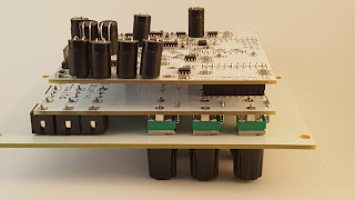
This module is based on ideas suggested by Lucas Abela.
It is three vactrol based bandpass filters in parallel, each filter is fed into a voltage controlled delay stage. The outputs are available individually or there is an OUT ALL where all 3 signals are mixed.
Me being me designed the delays to go into stutter/zipper/breakdown territory to create the usual noise I love. If desired the delays can be built to remain in their normal operating regions.
PCB set = USD25
Panel = USD26
Assembled = USD260
Build info on the NLC wiki
Steve's soundcloud demo
Engadine Maccas 97

nonlinearcircuits -
ANALOGUE modular synthesizers
(no midi, no software, no microprocessors)
PCBs and Modules LIST
Thursday 23 May 2019
DelayNoMore 3
This module contains three PT2399 delay chips that feed into each other to create a loop.
The delay time for each stage is individually CV controlled and each stage has feedback controls to itself and the previous stage.
Each delay stage can be isolated and used on its own so the module can be used as a triple delay or a 3 stage delay.....kind of:
If you are familiar with the original DelayNoMore, you will know it is a crap delay but an excellent noise module, this one is designed to be much the same. The big differences being 3 delay stages instead of 2, CV control over all 3 stages instead of 1 and, as mentioned, the stages can be used individually.
To use, the input signal(s) can be patched into the 1-3 inputs and the three outputs can ll be used to get different signals. The 2nd row of inputs use the jack switches to forward the output of each stage to the input of the next, so if you wish to use the delays individually, use these inputs to break the loop.
There are pads on the PCB to place resistors in parallel with the LDRs in the vactrols, this is to tame the delay times somewhat. It is up to the builder to decide how lame or how out of control they want this module to be.
PCB = USD22
Panel = USD26
assembled = USD240
build info on NLC wiki
Steve's soundcloud demo
Wednesday 8 May 2019
4HP MIX
The simplest module in the NLC range, a 4 input mixer. It has just 14 components to solder onto the PCB, so a very gentle intro to surface mount soldering.
The pots are 0 at centre, -1x gain to the left (inverts) and 1x gain to the right.
Pot 4 will act as a voltage offset if nothing is patched into input 4. It can supply -5V to +5V of offset. If you do not want any offset, leave pot 4 at midpoint, or patch your signal into input 4.
The module will work with audio and CV signals. It is useful for creating sequences from logic modules such as the Divide&Conquer, BOOLs or 1/n.
PCB & panel set = USD12
assembled = USD60
Subscribe to:
Posts (Atom)


